P200-SX Exhaust Jet Model & Duct Design
Graduate researchThis project takes a hot, fast jet out of a closed test cell, safely and without disturbing the engine. A MATLAB model of the free jet sized the ducting. A first concept failed because it set off the CO alarm. The installed duct carries the exhaust upward. The latest design work is a digital twin of the cell.
WhatWhat the exhaust has to do
The P200-SX sends a hot, high-speed jet into a closed room. The ducting has to:
- carry the jet out of the building without back-pressuring the nozzle
- entrain enough room air to cool and dilute the jet
- leave space for the sampling probe
- fit inside an existing cell.
To size the duct, I needed a quantitative picture of how the jet slows, cools and spreads, before any hardware or CFD.
How1 · A marching model of the free jet
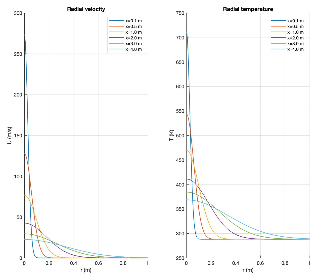
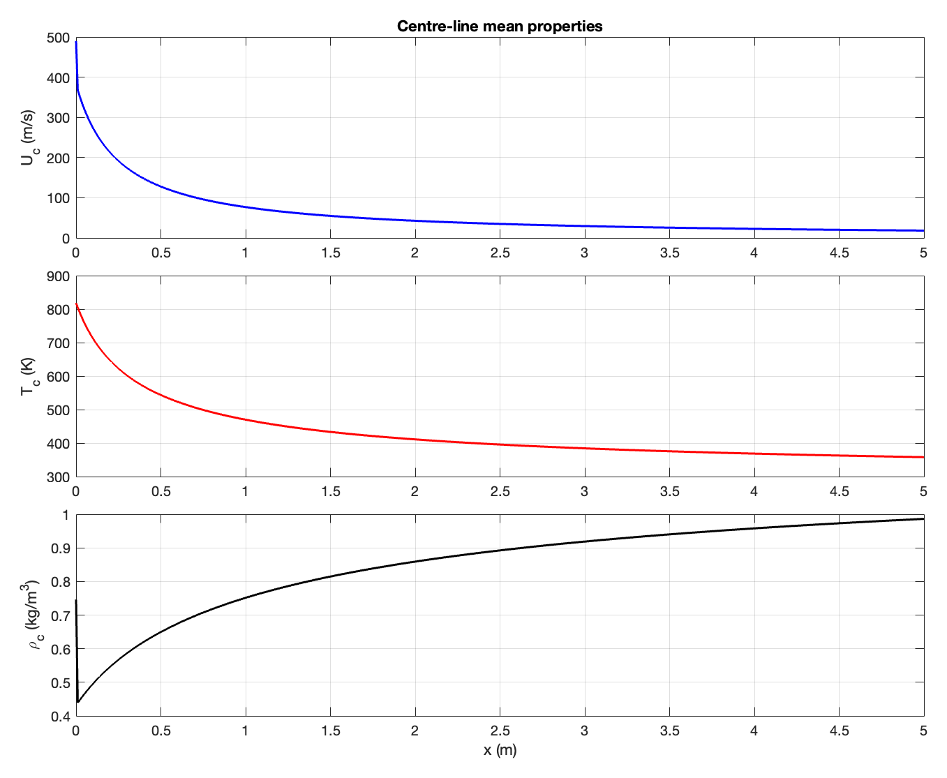
I modeled the exhaust as a free, axisymmetric turbulent jet in still air. A MATLAB marching model steps downstream from the nozzle. It uses Gaussian self-similar profiles, momentum and enthalpy conservation, a linear spreading rate and an eddy-viscosity closure, with constants from the turbulent-jet literature. The Method view in the gallery above shows the centerline decay.
Gaussian self-similar profile with half-width \(b(x)\), inverse centerline decay with constant \(B\) from the virtual origin \(x_0\), and linear spreading at rate \(S\). Temperature follows the same similarity, with enthalpy conservation.
The physics is simple. The momentum flux is conserved, so as the jet entrains still air, its width grows linearly and its centerline velocity falls as \(1/x\). I checked the decay trends against 0D estimates for both the velocity field and the thermal field.
Five meters downstream, the centerline has slowed to about 18 m/s and cooled to about 360 K. This prediction set the duct diameters. It also suggested that entrainment could supply the dilution the sampling system needs. The same geometry then became the domain for a 2D k–ω RANS model in ANSYS Fluent. That model gave a second estimate of the jet evolution and the flow uniformity in the duct.
How2 · The first concept, and why it was dropped
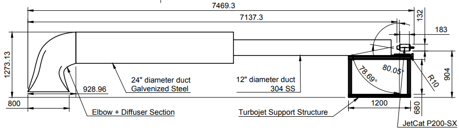
The first design, done in SolidWorks, was a dual duct that turned the exhaust down and away from the engine. Two problems ended it. First, in-house fabrication of the elbow and diffuser proved impractical. Second, a test of a simplified elbow showed that the turn itself was at fault. Directing the exhaust toward the floor caused enough recirculation to set off the test cell’s CO alarm. A duct that looks reasonable on paper can still return exhaust to the room.
How3 · The duct as installed
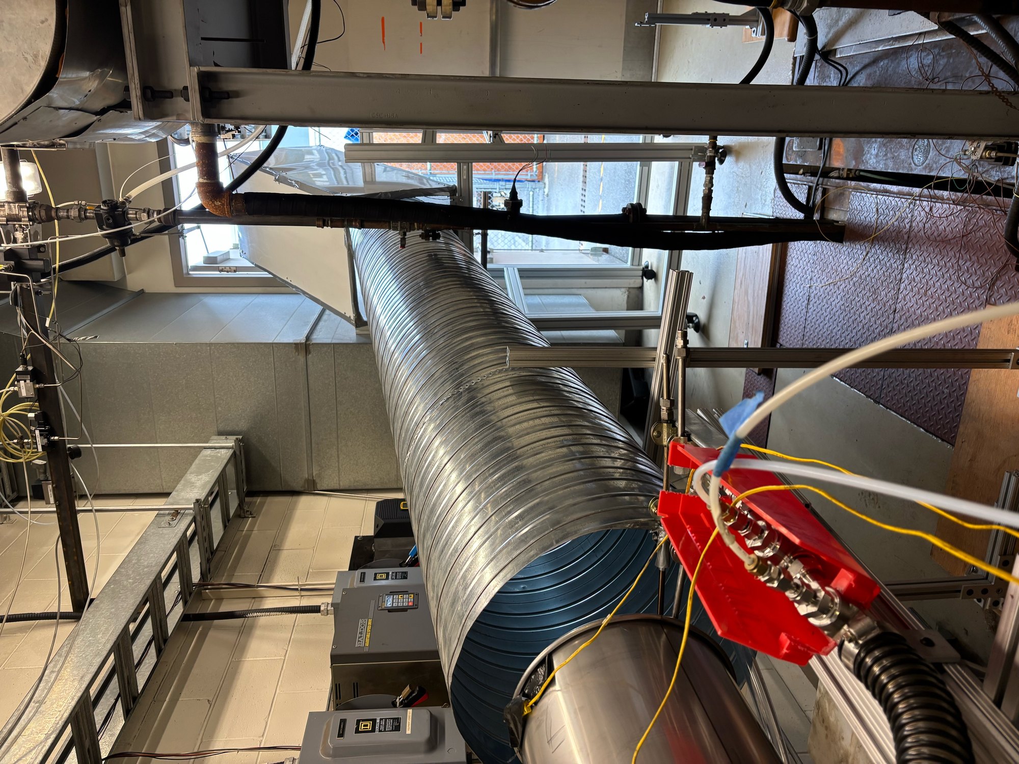
The installed duct deflects the exhaust about 30° upward into a straight run, away from the floor. A 12-inch section extended it in December 2025. The supports and probe mounts were built in-house from repurposed stock.
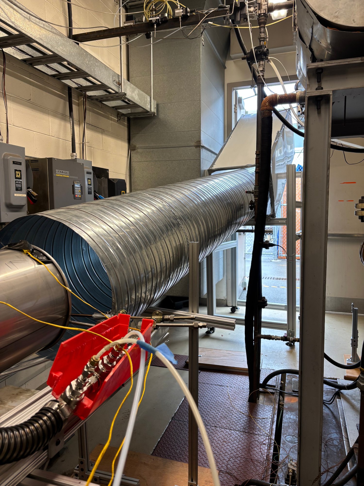
The exhaust is also sampled in the duct. The probe holder, thermocouples and lines are therefore part of the design from the start.
Results4 · A digital twin of the cell
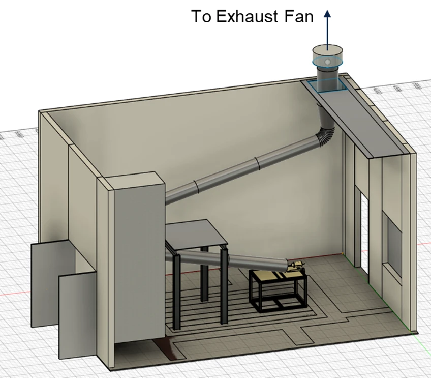
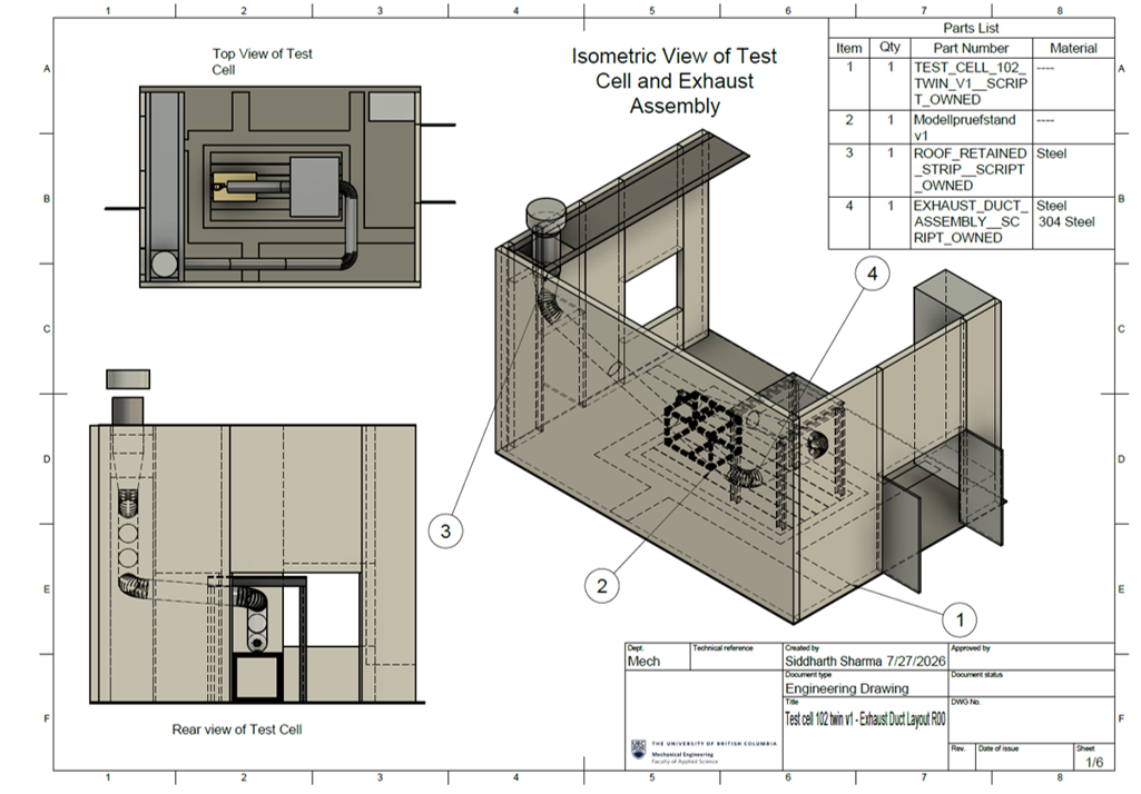
The latest design work is a digital twin of the whole test cell, shown as the Result view at the top. It is a CAD model of the walls, the engine stand, the roof-retained strip and the steel duct assembly. With it, a new route or a second engine can be checked against the real geometry before anything is cut. The layout drawing below is its first release (R00, July 2026).
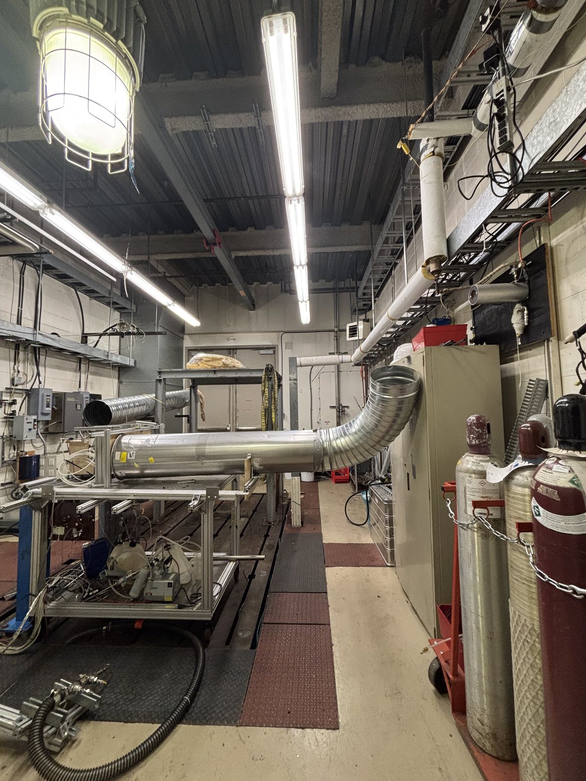
The newest setup work happens in the cell itself. I test layout options with the ducting and supplies we already have, and check them against the twin.