P220-RXi Station 4 Sampling Apparatus
Apparatus designThis apparatus adds a Station 4 sampling port to the P220-RXi casing, with a coaxial dilution probe that samples gas ahead of the turbine. The main purpose is to separate fuel-derived pollutants from lubrication-oil contributions, which exhaust measurements cannot isolate. I designed the probe with a coupled one-dimensional model, drew the probe and installation packages, and sent the designs out for fabrication of parts. No sample has been taken with the probe yet, so an oil-free sample is still a design objective.
WhatWhy sample at Station 4
The micro-turbojets in our test cell have an open-loop lubrication system. In the documented P200-SX architecture, lubrication oil is ejected into a small gap between the inner casing and the axial turbine. It enters the gas path and is not recirculated [1, 2]. The exhaust therefore contains lubricant products in addition to the products of the fuel.
An exhaust measurement cannot directly separate the two. Our earlier campaigns investigated the oil contribution only indirectly [2]:
- The emission indices use a carbon balance on the measured CO₂, CO and NOₓ.
- A switching valve sent the diluted sample either straight to the analyzers (bypass) or through a catalytic stripper first.
- The stripper oxidizes carbon-bearing volatiles to CO₂. The difference \(\Delta\mathrm{CO_2}=\mathrm{CO_{2,stripped}}-\mathrm{CO_{2,bypass}}\) measures the total volatile carbon.
- A total volatile organic compound (TVOC) analyzer saw volatiles in the bypass flow and none downstream of the stripper.
The difference stayed below 30 ppm at high thrust. It was below 6% of the total carbon at the lowest operating points, and it decreased with load [2]. Non-volatile particles held less than 1% of the fuel carbon [2]. These checks bound the unmeasured carbon, but they cannot tell combustion-derived hydrocarbons from lubricant volatiles [2]. The particle measurements may also include metal particles that come from the oil [3].
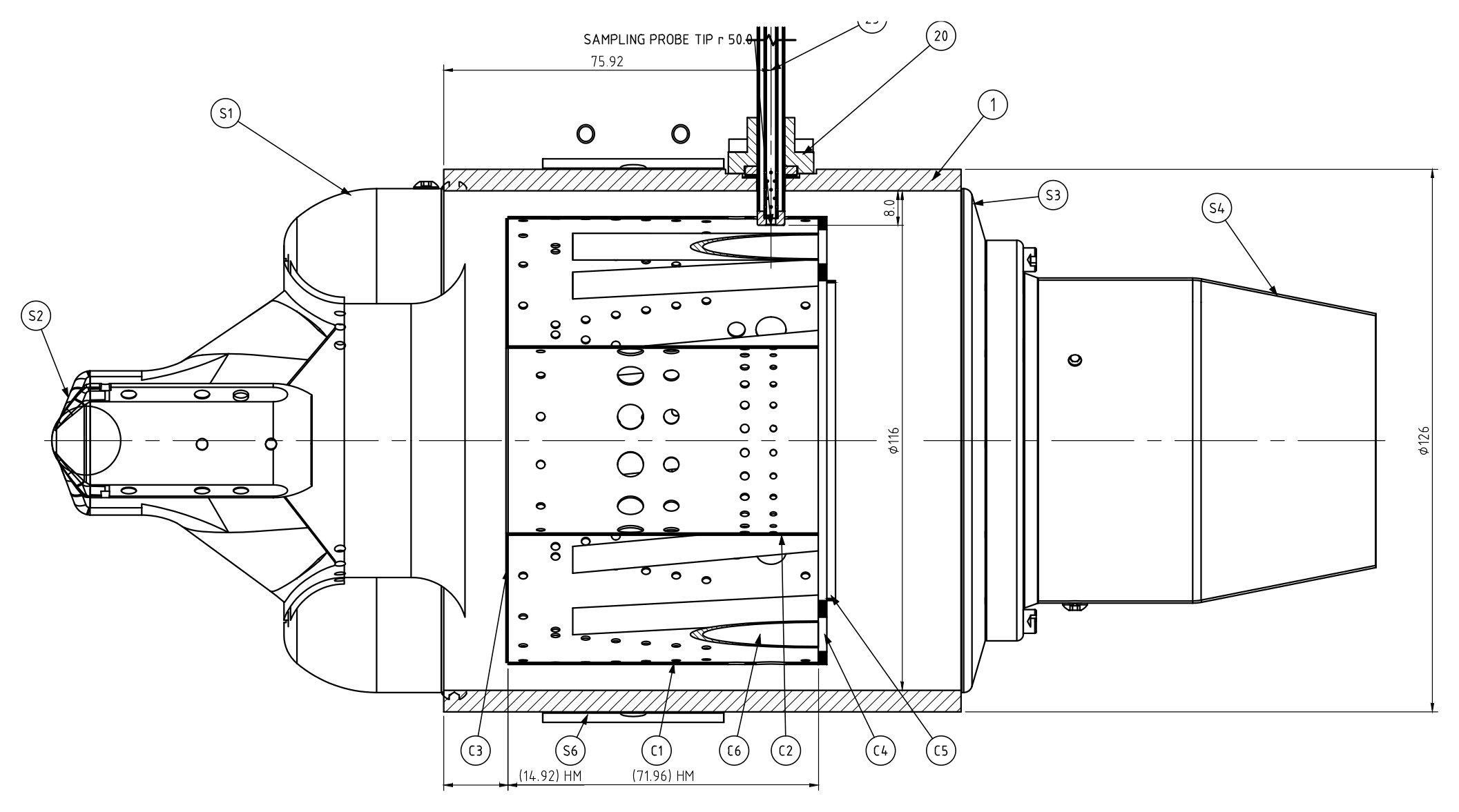
Station 4 is the combustor exit, ahead of the turbine. A sample taken there is upstream of the point where the documented lubrication flow enters the gas path. A Station 4 sample and an exhaust sample at the same condition then give a more direct comparison than exhaust data alone.
Two limits apply to this argument:
- In the documented campaigns the engine burned a blend of 95% Jet A and 5% lubricating oil [1]. One supply feeds both the combustor and the lubrication system. A Station 4 sample excludes the turbine-gap oil. It does not exclude oil that burns in the combustor with the fuel.
- The papers document the P200-SX. I have not found a document of the P220-RXi oil path, so this design takes the P200-SX description as its basis.
A related motivation is the chemical reactor network (CRN) of the combustor [1]. A Station 4 sample constrains the combustor-exit state that the CRN predicts. It comes from one tip position, so it does not uniquely validate the internal CRN zones.
HowProbe design development
The P220-RXi combustor annulus is about 6 mm deep. A probe must cross the casing, pass a liner dilution hole and stop short of the fuel vaporizer sticks. This limits it to a 6.35 mm outer tube. The probe must then draw hot gas, dilute it quickly at the tip and deliver it with a known dilution ratio (DR).
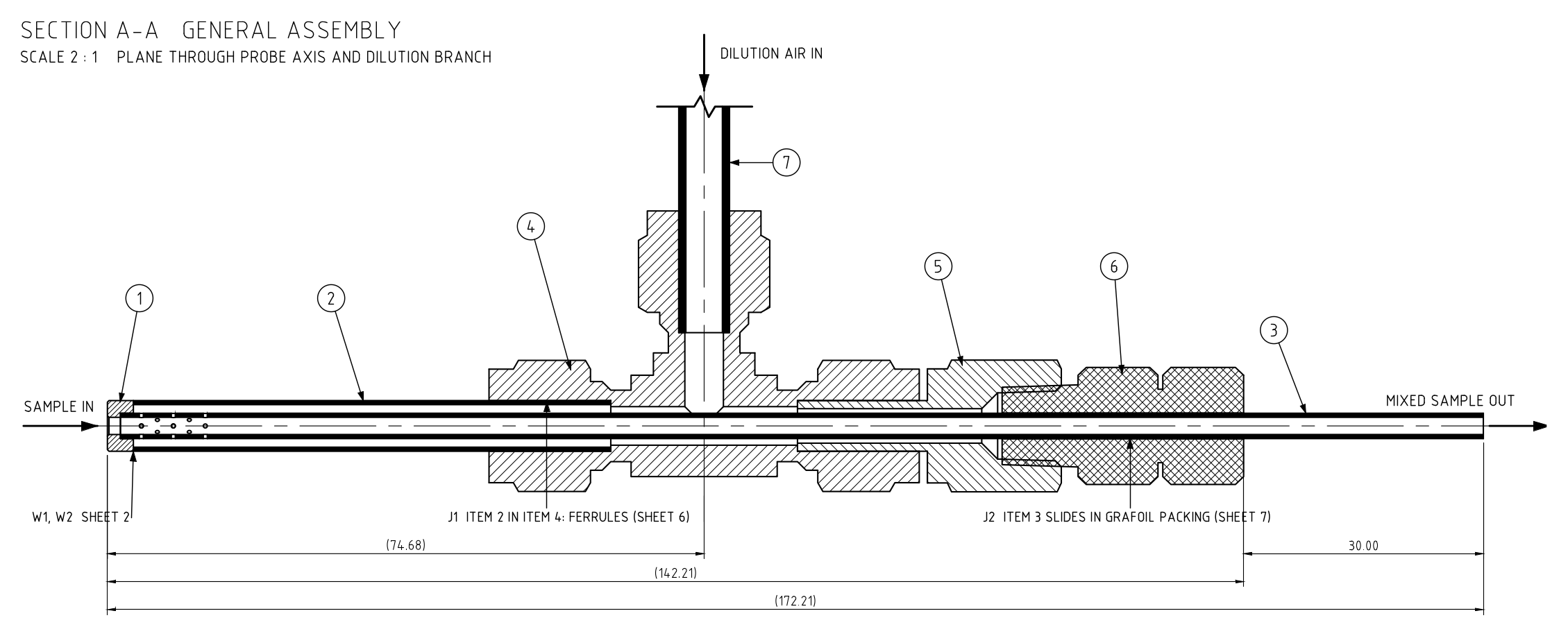
I chose a counterflow dilution probe with two concentric tubes. Sample gas enters the open inner bore at the tip and flows toward the base. Dilution air enters the annulus at the rear and flows toward the sealed tip. The two streams meet only through rows of small holes in the inner tube.
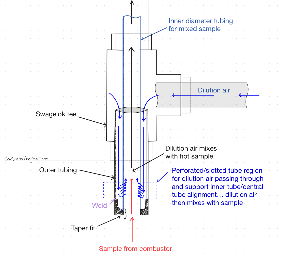
I started on paper. The sketch fixed the parts that every later revision kept. These are a tee for the dilution air, two concentric tubes, a perforated mixing region and a taper-fit tip.
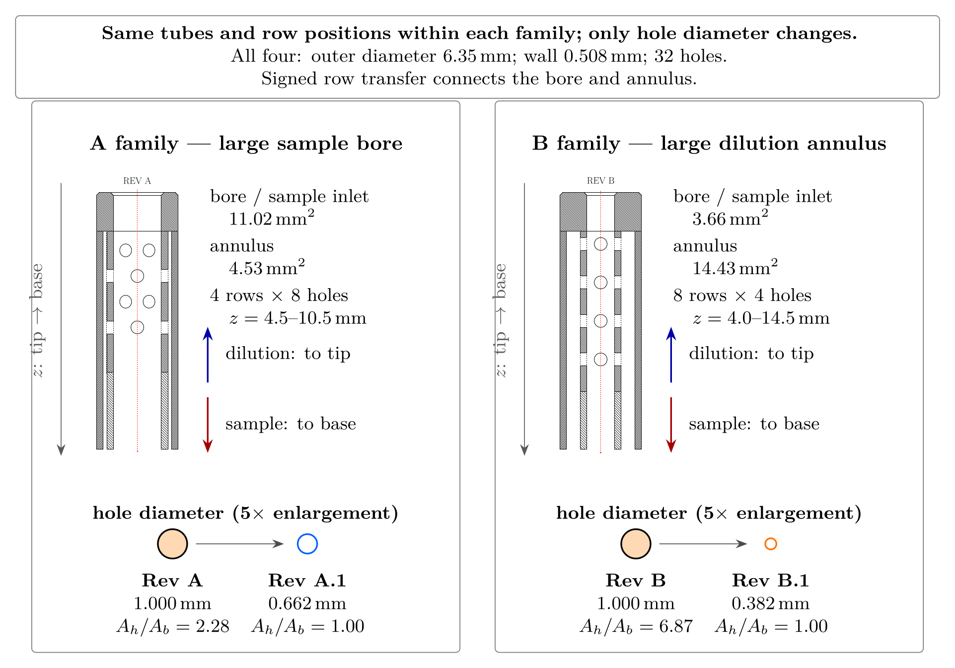
The first design study compared four configurations, built as a controlled experiment. It asked two questions:
- How should the cross-section be split? Rev A gives 11.02 mm² to the sample bore and 4.53 mm² to the annulus. Rev B reverses that, with 3.66 mm² and 14.43 mm².
- How strongly should the rows resist flow? Rev A.1 and Rev B.1 keep the tubes, rows and hole positions of their parent. They change only the hole diameter.
In the .1 variants, the total hole area equals the sample-inlet area of the probe:
For B.1 this gives 32 holes of 0.382 mm (\(A_h/A_b=1.00\)) in place of the 1.0 mm holes of Rev B (\(A_h/A_b=6.87\)). A smaller hole needs a larger pressure difference to pass the same mass, so the rows resist more.
HowWhy B.1 was chosen
The study used the first (MATLAB) version of the probe model software on the 32-hole geometries, with P200-SX operating points. Its findings are model predictions for those geometries only:
- The cross-section split sets capacity. The large-bore A family draws much more sample. The B family delivers a colder outlet stream at the same dilution command.
- Smaller holes redistribute the dilution. At one OP80 case, Rev B sent 93.8% of the forward row flow through its last row. B.1 sent 39.0%.
- Few searches reached the DR = 10 benchmark. Of 36 target searches, two found a continuous crossing, both at the highest-power operating point.
B.1 reached DR ≈ 10 at about 34 SLPM of dilution, inside the planned 2–50 SLPM command range. A.1 reached it with about 6.7 times more sample, but it needed about 227 SLPM. The two results used different exit-pressure settings, so they are not a matched comparison. B.1 was the only configuration that met the benchmark with a realistic dilution supply. Its cost is a small sample flow.
In that study, the B.1 bulk gas temperature fell by 90% of its total drop within 11 mm of the tip. The bulk residence time was about 0.9 ms. These are bulk one-dimensional values. They do not establish chemical freeze-out, particle preservation or a uniform quench.
HowThe fabrication layout
The computed 0.382 mm hole is not a drill size. For fabrication I kept the B.1 tubes and replaced the hole pattern with a drillable layout [4]:
- 20 holes of 0.50 mm, in 5 rows of 4, between 4.25 mm and 12.25 mm from the tip
- alternate rows clocked by 45°
- total hole area 107% of the 2.159 mm inlet bore area (the ±0.05 mm drilling tolerance alone spans 87–130%)
- a modeled length of 63.0 mm instead of the 60 mm of the study.
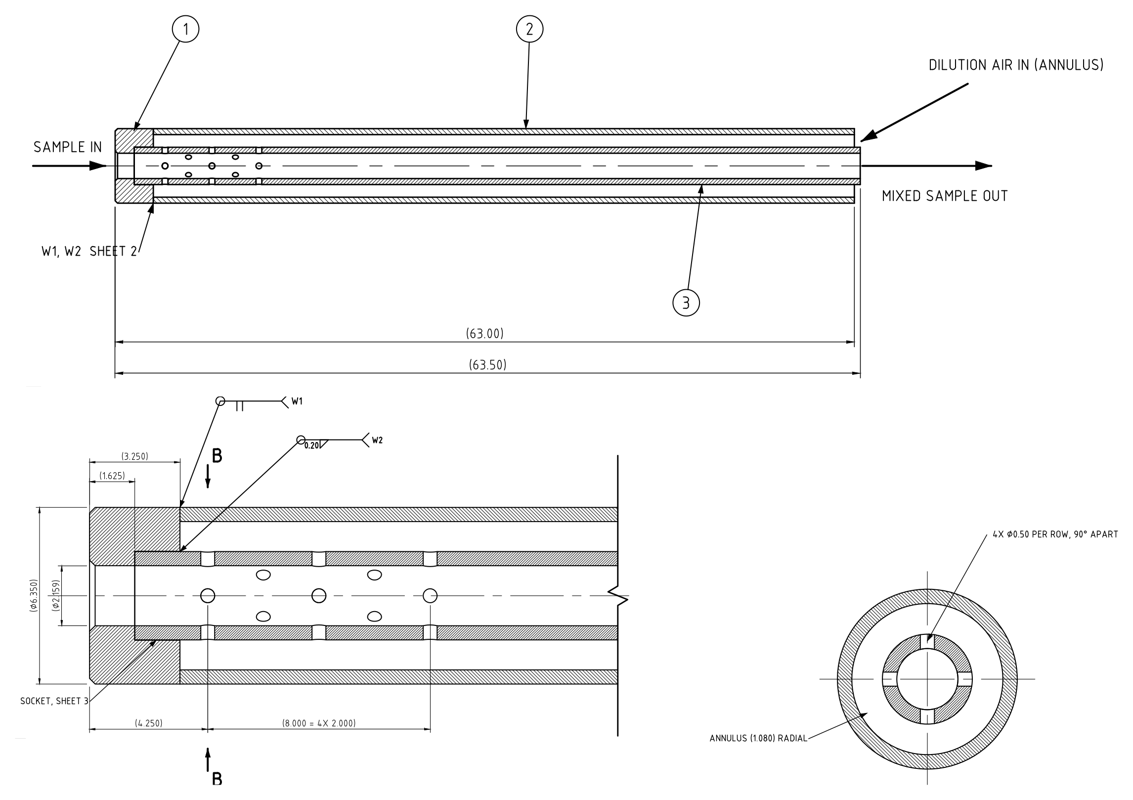
This layout differs from the studied geometry in row count, hole size, row positions and length. The 34 SLPM result and the other first-study numbers therefore do not apply to the fabricated probe. I solved the drawn geometry again with the second (Python) version of the model.
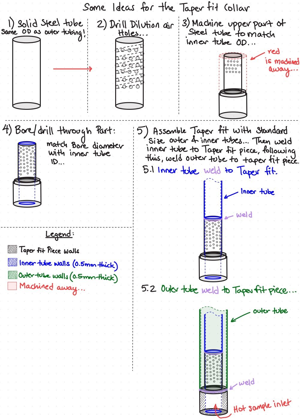
The tip is the hardest part to make. I sketched how to build the taper-fit collar from solid steel tube. The sketch also sets the order in which the two tubes are welded to it.
ResultsPredictions for the drawn geometry
The model searched for the bore-exit pressure that holds DR = 10 at three P200-SX operating points and four dilution commands. Eleven of the twelve combinations have a setpoint. At OP60 and 40 SLPM, the 2.159 mm bore chokes before the probe can draw enough sample.
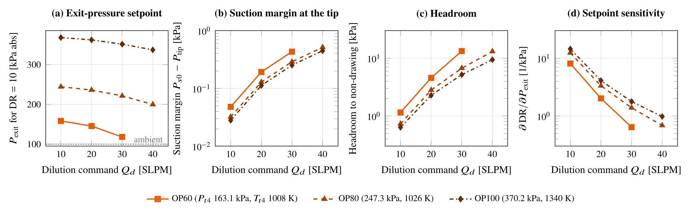
- At 30 SLPM the predicted setpoints are 118.1, 221.3 and 351.2 kPa absolute. All are above ambient, so a back-pressure regulator is enough and no pump is needed.
- The probe draws on a suction margin of less than 0.5 kPa. DR is therefore steep in the setpoint.
- Higher dilution commands move the setpoint away from the drawing limit. At 30 SLPM, a 0.1 kPa setpoint error moves DR by 0.06–0.18.
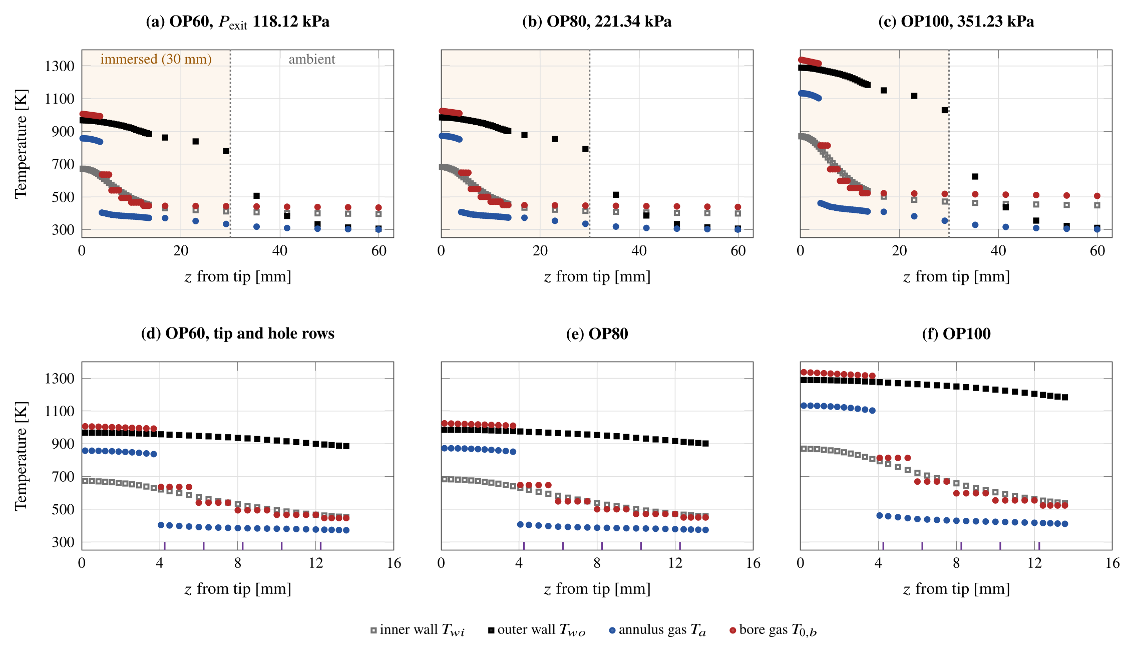
The predicted bulk bore gas leaves the probe at 434, 438 and 506 K at the three operating points. The outer wall is hottest at the tip, at 968, 986 and 1290 K. The model applies no material allowable. Whether 316 stainless steel is adequate at OP100 is not settled by this study.
HowCasing modification and installation
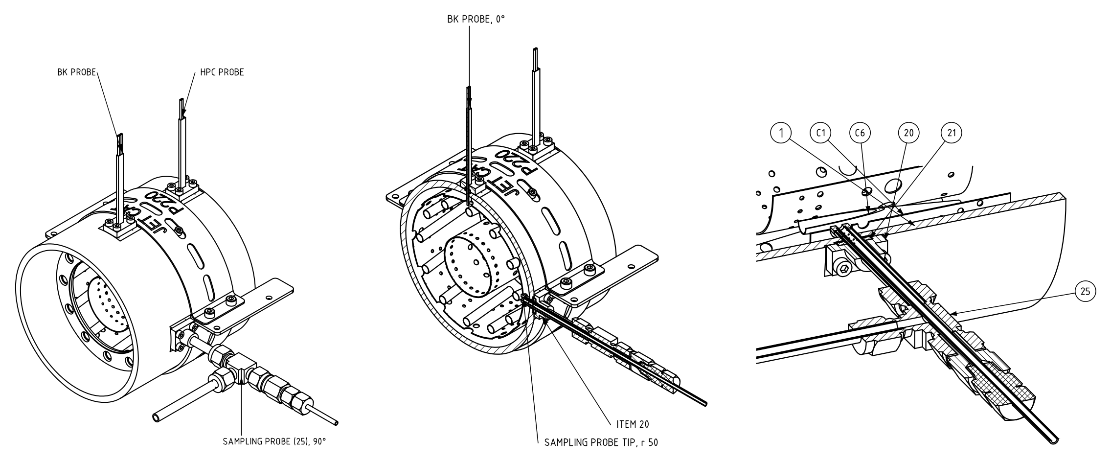
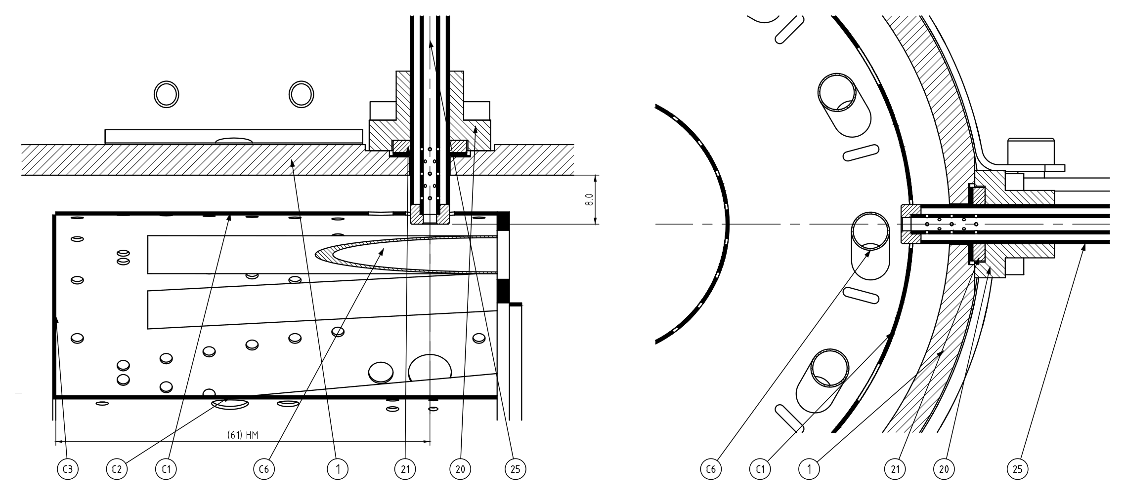
The probe enters the casing at Station 4, 90° around the engine from the existing BK total-pressure and thermocouple probe [4]. It passes a 7 mm liner dilution hole opened to 8 mm, which leaves 0.83 mm of radial clearance for liner growth. The tip sits 8.0 mm inside the casing bore, at the BK probe depth.
A brazed flange on a graphite gasket holds the probe to the casing. The flange position sets how much of the probe is immersed in combustor gas. A Swagelok union tee admits the dilution air. The inner tube leaves through a Grafoil packing gland, so the two tubes can expand by different amounts.
The installation package is toleranced to ISO 2768-m, with ISO 8015 independency and third-angle projection. It calls out every part, fastener and fitting. The combustor geometry comes from hand measurements, and every installation sheet carries that note.
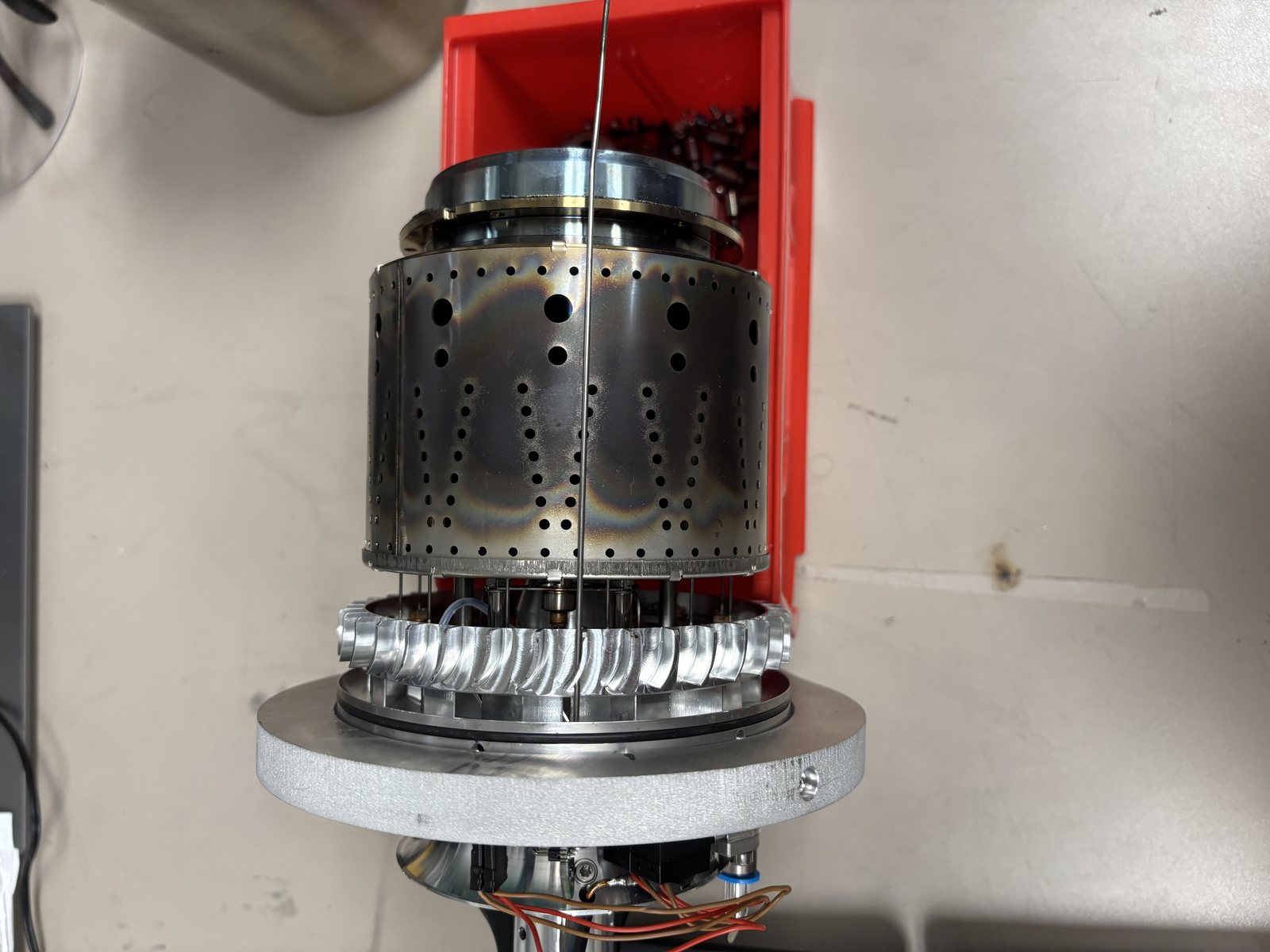
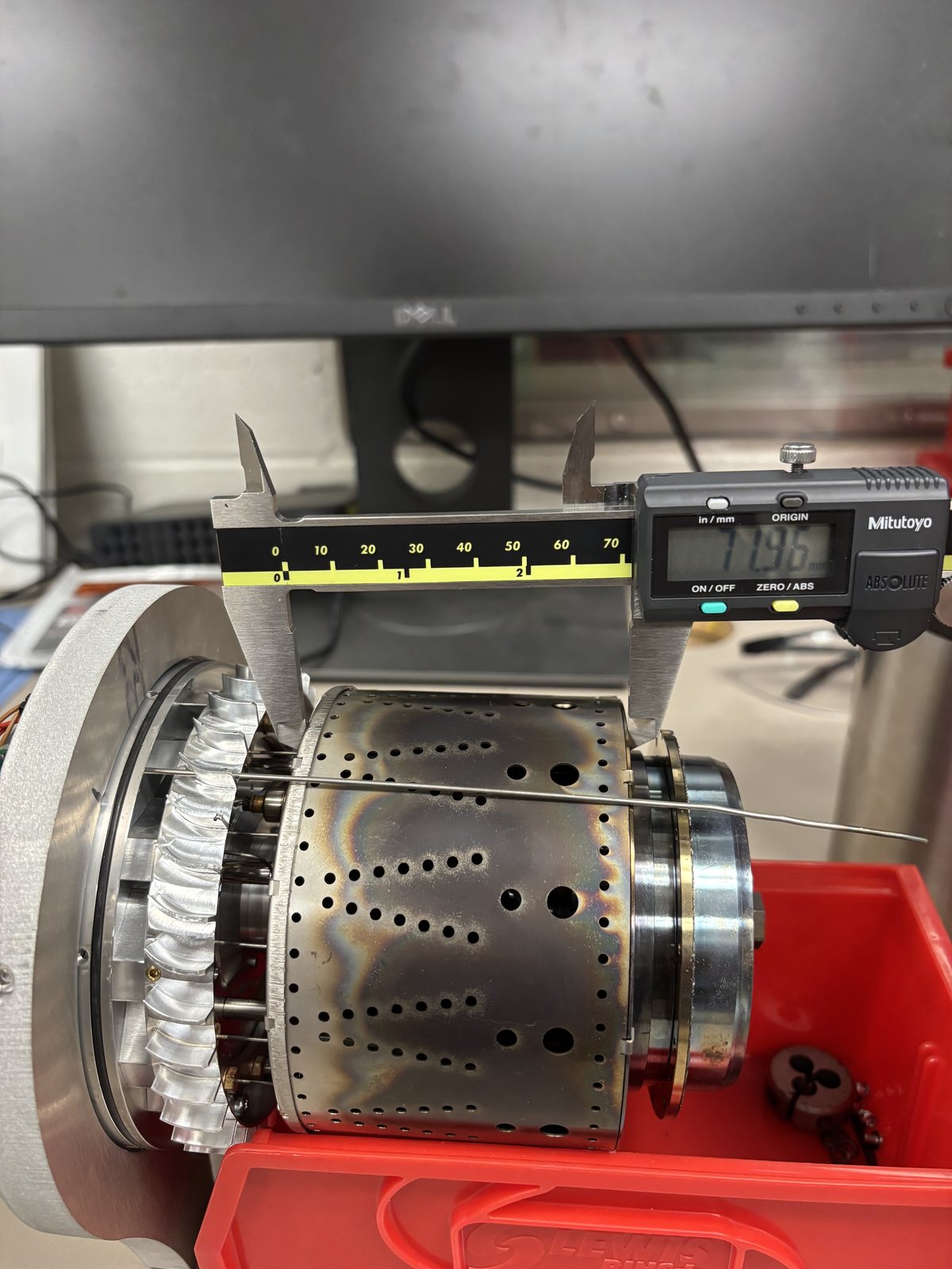
The modification package also covers the engine instrumentation around the probe:
- pressure and temperature measurement points
- a redesigned data-acquisition layout
- exhaust and entrainment sizing guided by MATLAB models
- short sampling lines, so that fewer of the smallest particles are lost before they are counted.
ResultsScope limits
- No measurement exists for this probe. The discharge coefficients, the immersed length and the hot-side heat transfer are model assumptions.
- The engine operating points come from the P200-SX, which is the development surrogate for the P220-RXi.
- The model is one-dimensional. It does not resolve jet mixing, chemistry, particle deposition or the analyzer line.
- An oil-free comparison sample is the design objective. It has not been demonstrated.
References
- [1]D. Lieder, S. Sharma, P. Kirchen, S. Rogak and J. Goeing, “Development of a validated chemical reactor network model for non-CO₂ emissions in RQL aircraft combustors,” ASME Journal of Engineering for Gas Turbines and Power, accepted (GTP-26-1516); Proc. ASME Turbo Expo 2026, GT2026-177253, Milan.
- [2]S. Sharma, D. Lieder, S. Saini, A. Kumar, P. Kirchen, J. Goeing and S. Rogak, “A micro-turbojet test rig to analyze the impact of jet fuels on emissions and performance,” Proc. CSME International Congress / 33rd Annual Conf. CFD Society of Canada, Vancouver, May 2026, Paper 361.
- [3]D. Lieder, S. Sharma, H. Lintusaari, N. Sapkota, A. Kumar, P. Kirchen, J. Friedrichs, S. Rogak and J. Goeing, “Measurement and prediction of particle emissions from a micro turbojet using conventional and alternative jet fuel,” Proc. GPPS Montreal26, GPPS-TC-2026-102, 2026, doi:10.33737/gpps26-tc-102. © the authors, CC BY-NC-ND 4.0.
- [4]S. Sharma, drawing packages EM-P220-SP (19 sheets), PS-RB1-SC (6 sheets) and PS-RB1-SCT (8 sheets), Rev. A, preliminary, UBC Mechanical Engineering, 7 October 2026.