MECH 484: Tapered vs Delta Wings
Course projectA group research project in aircraft aerodynamics (MECH 484, 2024). We reviewed how tapered and delta planforms work. We then used simplified course formulas on the F-111’s two sweep positions, and compared two reconnaissance aircraft, the U-2 and the SR-71.
WhatWhat the project asked
How does wing planform change an aircraft’s performance? The F-111F has a variable-sweep wing. With the wings spread, it has a tapered, high-aspect-ratio “glider” position. With the wings swept back, it has a low-aspect-ratio, delta-like position.
We used one airframe in two positions. This removes some differences between aircraft. But sweep, aspect ratio and wing area all change together, so the comparison is between two configurations.
| Configuration | Aspect ratio | Wing area |
|---|---|---|
| Tapered (glider, wings spread) | 7.56 | 657.4 ft² |
| Delta-like (swept) | 1.95 | 525 ft² |
WhatThe two planforms
Tapered wings narrow in chord from root to tip. A high aspect ratio and a suitable taper ratio move the lift distribution toward the elliptical ideal. This weakens the tip vortices, which cause the induced drag. Such wings also tend to stall inboard first, so the ailerons stay effective longer.
Span \(b\), wing area \(S\), tip and root chords \(c_t,c_r\). The second term of the drag polar is the induced drag. At the same lift it decreases as \(AR\) increases. This is the low-speed, subsonic form of the polar.
Delta wings are highly swept. Sweep splits the oncoming flow into a chordwise part and a spanwise part. Only the chordwise part sets the shock behavior, so sweep delays the critical Mach number.
At high angle of attack, the sharp leading edges shed stable vortices along the upper surface. Their low pressure adds vortex lift, so a delta keeps lifting where a conventional wing would stall. In supersonic flight, thin-airfoil theory gives the lift and the wave drag:
Angle of attack \(\alpha\) and free-stream Mach number \(M\). These are two-dimensional flat-plate results. The cost of a delta’s strengths is a low aspect ratio, and with it high induced drag at subsonic cruise.
HowThe simplified performance model
We used formulas from the course notes for both positions:
- cruise thrust required at 920 ft/s and 50,000 ft
- glide ratio as the lift-to-drag ratio, with no wind and a small angle of attack
- climb rate at sea level from excess power
- turn rate at a 20° bank and 50,000 ft.
Steady level cruise needs thrust equal to drag. Climb rate is the excess of available power \(P_a\) over required power \(P_r\), divided by the weight \(W\).
ResultsWhat the estimates can and cannot show
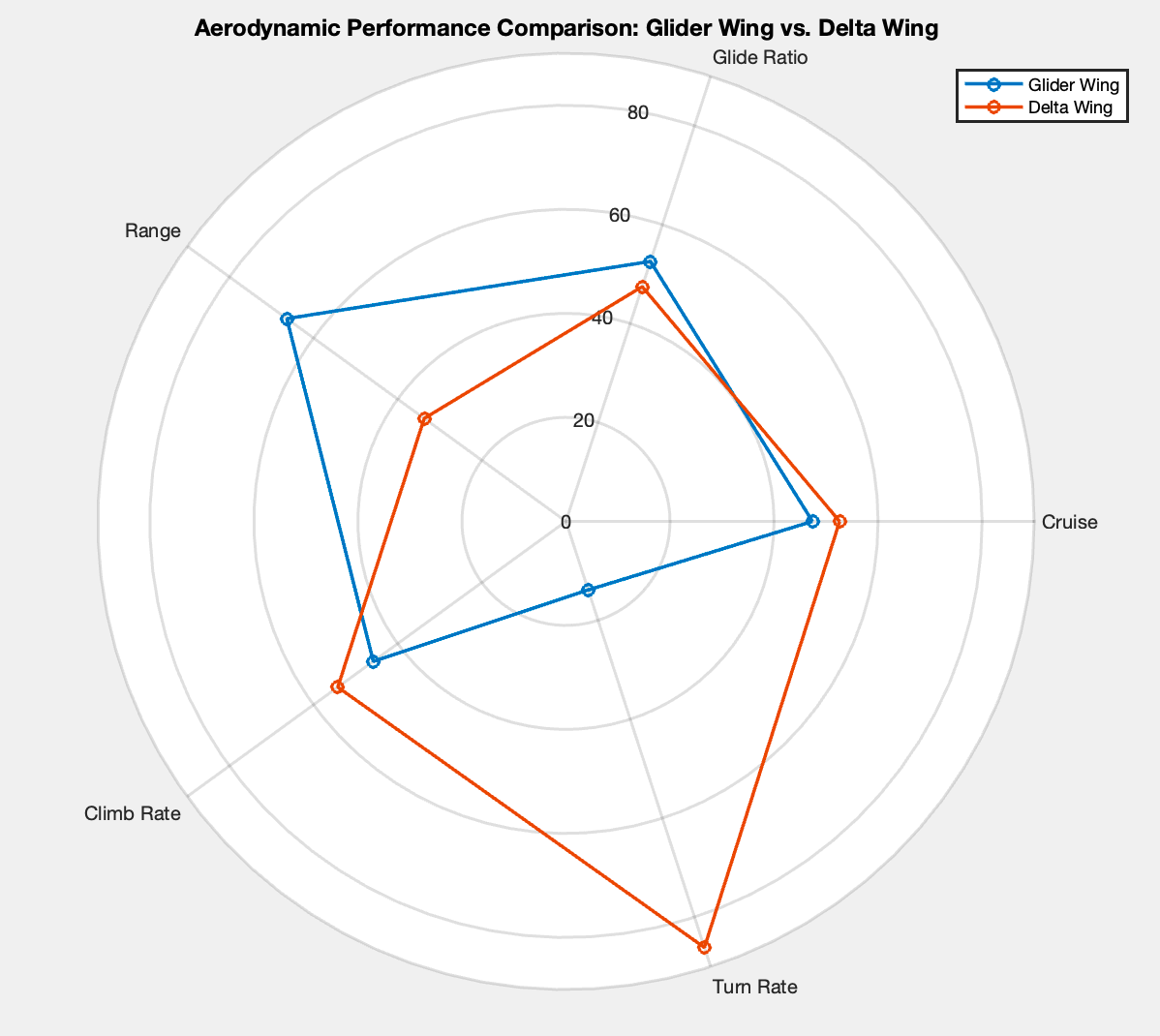
Looking back, three parts of the model do not hold up:
- Transonic cruise. At 50,000 ft, 920 ft/s is about Mach 0.95. The subsonic drag polar has no compressibility or wave-drag term, so it cannot give reliable cruise thrust or lift-to-drag values at this speed.
- Range basis. The range estimate used a power-specific fuel consumption (0.5 lb/hp·hr) in a propeller-type range relation. The F-111F has afterburning turbofans, which need a thrust-specific fuel consumption and the jet form of the range equation.
- Turn-rate constraint. In a level, coordinated turn at a fixed bank angle, the turn rate is \(g\tan\phi/V\). It depends only on the speed. A different turn rate at the same 20° bank therefore implies a different speed, which the report does not state.
I do not quote the range or turn-rate results here. The drag coefficients for the two positions are also not documented in the report. The table below lists only the remaining estimates, as course-model outputs.
| Course-model estimate | Tapered (glider) | Delta-like (swept) | Main limitation |
|---|---|---|---|
| Cruise thrust required (920 ft/s, 50,000 ft) | 5,500 lbf | 6,100 lbf | Subsonic polar at about Mach 0.95 |
| Glide ratio \(C_L/C_D\) | 15.09 | 13.65 | Drag inputs not documented |
| Climb rate (sea level) | ≈ 8,300 fpm | ≈ 9,800 fpm | Speed and weight not stated |
The two positions give comparable cruise thrust and glide ratio in this model. That is as far as the numbers go. The broader trade-off, a high aspect ratio for efficient subsonic flight and strong sweep for high speed, comes from the literature.
ContextCase studies: U-2 and SR-71
Both aircraft flew high-altitude reconnaissance, with opposite aerodynamic answers. The U-2’s long, high-aspect-ratio wing gives a high lift-to-drag ratio in thin air for endurance. It lets the aircraft glide and use updrafts to save fuel, and its design guards against flutter.
The SR-71’s delta-like wing is built for Mach 3+. Thin sections and sharp leading edges reduce wave drag, and vortex lift helps at take-off and landing. A titanium structure tolerates the aerodynamic heating. One aircraft trades speed for time over the target, and the other trades loiter time for fast entry and exit.